

close
Choose Your Site
Global
Social Media
Views: 0 Author: Site Editor Publish Time: 2026-08-26 Origin: Site


Premature drive belt failure in high-torque, continuous-duty applications results in unacceptable production downtime, compromised harvest schedules, and inflated maintenance budgets. Specifying the correct power transmission component requires navigating complex variables, including start-up torque, shock loads, environmental contamination, and sheave compatibility. Generic replacements often fail to address the specific mechanical demands of heavy-duty industrial and agricultural equipment.
This guide provides an engineering-led framework for evaluating, specifying, and implementing V‑Belts and alternative drive solutions. It breaks down technical evaluation criteria, step-by-step sizing workflows, and replacement indicators to help procurement and maintenance teams maximize power transfer efficiency and equipment uptime. Understanding the physics of power transmission allows maintenance professionals to move beyond reactive replacements and engineer robust, long-lasting drive systems.
Matching belt cross-sections (e.g., A, B, C, 3V, 5V) to exact sheave dimensions is the foundational requirement for optimal wedging action and slip reduction.
Accurate service factor calculations are critical; industrial compressors require adjustments for high start-up torque, while agricultural machinery demands buffers for sudden shock loads.
While V-Belts dominate high-torque applications, specific high-speed or fixed-center drives may warrant the evaluation of a Flat Transmission Belt or Elastic Flat Belt.
Over 90% of early-stage belt failures stem from improper tensioning and sheave misalignment during installation, making rigorous implementation protocols as important as product selection.
Industrial compressors, particularly large reciprocating and rotary screw models, present unique mechanical challenges for power transmission systems. These machines generate massive initial start-up torque to overcome the inertia of heavy internal components and pressurized chambers. The drive system must absorb this sudden energy spike without slipping or burning the rubber compound against the sheave grooves. Once running, continuous load profiles demand belts that maintain precise tension over thousands of operating hours without excessive elongation.
Heat dissipation represents another primary success criterion. Enclosed compressor housings often trap thermal energy, raising the ambient operating temperature significantly. Drive components operating in these environments must dissipate heat efficiently to prevent premature degradation of the synthetic rubber compounds. When thermal limits are exceeded, the belt hardens, loses flexibility, and eventually cracks. This leads to sudden catastrophic failure during operation. Upgrading to EPDM (Ethylene Propylene Diene Monomer) rubber compounds often extends operational life in these high-heat enclosures compared to standard neoprene.
Agricultural equipment operates in some of the most unforgiving environments imaginable. Combines, balers, forage harvesters, and heavy tractors face constant exposure to field dust, abrasive chaff, mud, and extreme seasonal temperature fluctuations. Abrasive particulates act like sandpaper against sheaves and belt sidewalls. This accelerates wear rates exponentially compared to clean indoor industrial settings. The chosen drive components must feature rugged outer covers capable of resisting this constant abrasion while protecting the internal load-carrying cords.
Agricultural machinery is also highly susceptible to severe, sudden shock loads. A rock entering a rock trap, a dense plug of damp crop material jamming a combine rotor, or the rhythmic heavy impact of a square baler plunger all send violent force spikes through the drive system. The transmission components must possess the exact right balance of tensile strength to handle the load and slight elasticity to absorb the shock. If the system is too rigid, the shock load transfers directly to the shafts and bearings, causing severe mechanical damage to the gearbox or engine.
The fundamental mechanical advantage of trapezoidal profiles lies in the physics of the wedging action within the sheave groove. As tension increases and the load is applied, the belt pulls deeper into the V-shaped groove. This wedging effect multiplies the normal force against the sidewalls, generating immense grip and torque transfer capabilities. This design inherently prevents slip under variable and pulsating loads, making it the standard for heavy-duty power transmission.
Beyond pure grip, these profiles offer distinct operational advantages over traditional chain and gear drives. They require absolutely no lubrication, eliminating a major maintenance variable and preventing oil or grease contamination in sensitive environments. The flexible rubber construction dampens mechanical vibration naturally. This isolates the driven equipment from engine pulsations and protects delicate connected bearings and shafts from premature fatigue.
While wedged profiles dominate high-torque applications, specific niche scenarios prioritize high-speed, low-torque power delivery. In these instances, evaluating a Flat Transmission Belt becomes necessary. These components excel in applications requiring extreme flexibility over very small pulley diameters. A standard trapezoidal profile forced around a miniature pulley will suffer from severe bending stress, leading to rapid heat buildup and structural cracking.
A standard Flat Belt sheds heat rapidly due to its thin cross-section and high surface-area-to-volume ratio. This makes it ideal for continuous, ultra-high-speed operations such as industrial blowers, precision grinders, and specific textile machinery. Because they do not rely on a wedging action, they operate with exceptional smoothness and minimal vibration at speeds that would cause heavier belts to whip or thrash.
Certain light-duty industrial conveyors and specialized agricultural sorting equipment utilize fixed center distance drives. These systems lack mechanical tensioning adjustments, sliding motor bases, or idler pulleys. An Elastic Flat Belt is engineered specifically for these constraints. It maintains inherent operational tension through a highly engineered elastic core that stretches during installation and continuously pulls tight during operation.
When analyzing the trade-offs, elastic variants provide superior vibration dampening and simplify machine design by eliminating tensioning hardware. However, they cannot match the heavy load-carrying capacity or shock-load resistance of traditional wedged profiles. Their use is strictly limited to applications where the maximum torque remains well below the threshold that would cause an elastic core to over-stretch or slip.
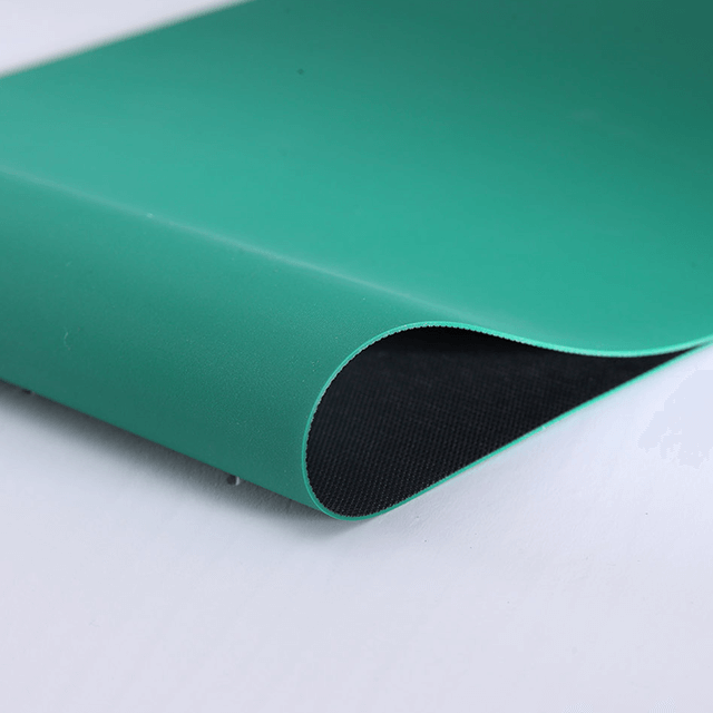
Selecting the optimal power transmission component requires matching specific engineering dimensions to the operational demands of the equipment. The following table summarizes the primary construction types and their operational characteristics.
Construction Type | Flexibility | Heat Resistance | Shock Load Capacity | Primary Application Environment |
|---|---|---|---|---|
Wrapped (Envelope) | Moderate | Standard | High | Agricultural, High-Dust, Clutching Drives |
Raw Edge Cogged | High | Excellent | Moderate | Industrial Compressors, Compact Drives, High Heat |
Banded (Joined) | Low | Standard | Extreme | Heavy Crushers, Pulsating Loads, Multi-Groove |
Flat Profile | Extreme | Excellent | Low | High-Speed, Small Pulley, Low-Torque Drives |
Understanding cross-section profiles is the first step in technical evaluation. Classical profiles, designated by letters like A, B, C, and D, represent the traditional standard. They feature a wider top width relative to their depth. This geometry offers broad compatibility across older machinery and handles standard loads effectively. Narrow profiles, designated by numbers and letters like 3V, 5V, and 8V, feature a deeper wedge shape. This geometry provides a significantly higher power density ratio, allowing narrow belts to transmit more horsepower in a more compact drive space. A single 5V profile can often carry the same load as three standard B-section profiles.
Precise sheave matching is non-negotiable. Installing a B-section belt in a 5V sheave will result in immediate failure, as the angles and depths do not align, destroying the wedging action. Engineers must calculate the pitch length rather than relying solely on the outside circumference. The pitch line is the neutral axis within the belt that neither compresses nor stretches as it bends around the sheave. Sizing based on pitch length ensures exact tensioning and prevents bottoming out in the groove.
Wrapped, or envelope, belts feature a fabric cover surrounding the internal rubber core and tensile cords. This fabric cover serves multiple purposes. It allows for momentary, controlled slip during clutching applications without destroying the rubber. More importantly for agricultural use, the fabric cover highly resists abrasive dust, chaff, and dirt. When operating a combine harvester in dry, dusty conditions, wrapped construction prevents particulates from rapidly chewing through the belt structure.
Raw edge cogged belts lack this fabric cover on the sidewalls, exposing the inner rubber compound directly to the sheave. They feature precision-molded notches, or cogs, along the inner circumference. These cogs drastically increase flexibility, allowing the belt to wrap around much smaller sheave diameters without cracking. The exposed rubber provides a higher coefficient of friction for maximum grip, and the cogs act like fan blades to dissipate heat effectively. This makes raw edge cogged construction the ideal choice for compact, heat-intensive industrial compressors.
Never size a drive system based solely on the motor's nameplate horsepower. Base horsepower ratings require adjustment using a service factor to account for the prime mover and the driven machine's duty cycle. An electric AC motor driving a continuous, smooth-running centrifugal pump might use a service factor of 1.1. However, a high-torque diesel engine driving a shock-prone agricultural rock crusher might require a service factor of 1.6 or higher.
Driven Machine Type | AC Motor (Normal Torque) | AC Motor (High Torque) | Diesel Engine (4+ Cylinders) |
|---|---|---|---|
Light Duty (Fans, Centrifugal Pumps) | 1.0 - 1.1 | 1.1 - 1.2 | 1.2 - 1.3 |
Medium Duty (Rotary Compressors, Line Shafts) | 1.1 - 1.2 | 1.2 - 1.3 | 1.3 - 1.4 |
Heavy Duty (Reciprocating Compressors, Mills) | 1.3 - 1.4 | 1.4 - 1.5 | 1.5 - 1.6 |
Extra Heavy Duty (Crushers, Agricultural Harvesters) | 1.4 - 1.5 | 1.5 - 1.6 | 1.6 - 1.8 |
The service factor accounts for the severity of start-up torque, the frequency of shock loads, and whether the operation is intermittent or continuous. To determine the design horsepower, multiply the drive motor's rated horsepower by the appropriate service factor found in manufacturer engineering tables. Sizing the drive to the design horsepower ensures the system possesses the necessary structural integrity to survive real-world operational spikes.
Implementing a rigorous selection workflow prevents specification errors and ensures maximum system reliability.
Determine the design horsepower by applying the correct service factor to the drive motor's rated horsepower based on application severity.
Select the optimal cross-section (e.g., B, C, 5V) by plotting the design horsepower against the RPM of the fastest shaft on a manufacturer's selection chart.
Calculate the required speed ratio by dividing the RPM of the faster shaft by the RPM of the slower shaft. Select appropriate sheave diameters to achieve this ratio while ensuring the smallest sheave exceeds the minimum recommended diameter to prevent excessive bending stress.
Determine the required center distance between the two shafts and calculate the final pitch length required for procurement. Verify that the chosen length allows for sufficient installation clearance and future tensioning take-up.
The internal tensile cords act as the muscle of the power transmission system, carrying the actual load. Standard duty applications typically utilize polyester tensile cords, which offer a good balance of strength and flexibility. High-stress applications demand premium materials. Kevlar or aramid tensile cords provide exceptional tensile strength and virtually eliminate operational stretch.
In heavy agricultural machinery subjected to violent shock loads, aramid cords resist snapping and maintain tension far better than polyester. Upgrading to premium cord materials directly extends the operational lifecycle. This extended lifespan reduces the frequency of maintenance interventions, which is particularly valuable in remote agricultural settings where equipment failure in the middle of a field causes severe operational disruption.
Equipment manufacturers often use proprietary OEM part numbers to obscure the standard dimensions of their drive components. Cross-referencing these proprietary numbers with standard aftermarket equivalents requires strict attention to dimensional accuracy, top width, groove angle, and load capacity. Utilizing manufacturer interchange guides ensures the aftermarket replacement matches the exact engineering specifications of the original component.
When replacing components on multi-groove drives, mixing different brands, or combining old and new belts, introduces severe operational risks. Even slight variations in manufacturing tolerances or the natural stretch of an older belt will cause uneven load distribution. The newer or slightly shorter belt will carry the entire load, leading to rapid, premature failure. Always install completely new, factory-matched sets to ensure uniform tension and load sharing across all grooves.
Power transmission efficiency directly impacts the energy consumption of industrial compressors. Belt slip is a primary source of energy loss, typically ranging from 2% to 5% in standard, moderately maintained configurations. This inefficiency translates directly to reduced compressor output and wasted electrical energy. When a belt slips, the motor turns, but the compressor shaft does not rotate at the intended speed.
Upgrading to premium raw edge cogged profiles minimizes slip due to their higher coefficient of friction. This maximizes energy transfer efficiency. Maintaining precise tension protocols further eliminates slip-induced energy loss. The operational returns of implementing high-efficiency drive components and strict maintenance schedules manifest in optimized compressor output and reduced electrical draw over the equipment's lifecycle.
Relying on run-to-failure maintenance strategies guarantees catastrophic downtime. Maintenance teams must identify visual and operational cues that signal impending failure. Visual inspections should look for cracked sidewalls, which indicate severe heat damage or bending stress from undersized sheaves. Glazing, a shiny, hardened appearance on the sidewalls, confirms chronic slipping and friction-induced heat buildup. Fraying covers or separated layers demand immediate replacement.
Operational cues often precede visual damage. A loud squealing noise during start-up or acceleration clearly indicates insufficient tension and severe slipping. A noticeable loss of driven RPM, detected via tachometer, shows the drive is failing to transmit full power. Excessive vibration or a rhythmic slapping sound suggests the tensile cords have stretched unevenly or the component has suffered internal structural damage.
Improper tensioning accounts for the vast majority of premature failures. Under-tensioning causes slip, glazing, and rapid sidewall wear. Over-tensioning places excessive radial loads on shafts, destroying motor and compressor bearings. Traditional spring-loaded deflection force gauges provide a baseline, but sonic tension meters offer vastly superior accuracy. By plucking the span and measuring the exact vibration frequency, technicians can set tension to precise engineering specifications.
Sheave alignment is equally critical. Misalignment forces the belt to enter the groove at an angle, causing accelerated, uneven sidewall wear and drastically reducing the lifespan. Relying on a straightedge or string line is insufficient for heavy-duty drives. Laser alignment tools project a precise beam across the sheave faces, allowing technicians to correct angular and parallel misalignment to within fractions of a degree.
When a failure occurs, diagnosing the root cause prevents the replacement from suffering the same fate. "Bottoming out" happens when the sidewalls wear down, allowing the belt to drop to the bottom of the sheave groove. It loses its wedging action entirely and rides on its bottom surface, requiring immediate sheave replacement. Cord pop-out, where the internal tensile cords break through the outer cover, points to severe shock loads or the improper practice of prying the belt onto the sheave with a screwdriver during installation.
Failure Symptom | Probable Root Cause | Corrective Action |
|---|---|---|
Rapid Sidewall Wear | Severe sheave misalignment or worn grooves. | Realign sheaves using a laser tool; replace worn sheaves. |
Hardened, Glazed Sidewalls | Chronic slipping due to under-tensioning. | Replace belt and tension to manufacturer specifications using a sonic meter. |
Bottom Cracking | Excessive heat or sheave diameter too small. | Improve ventilation; upgrade to raw edge cogged construction. |
Belt Rollover in Groove | Heavy shock loads or pulsating vibrations. | Upgrade to banded (joined) belt configurations. |
Tensile Cord Breakage | Prying belt onto sheave during installation. | Loosen motor base fully before installing new belts; never pry. |
Belt rollover, where the component flips upside down in the sheave groove, plagues multi-groove drives subjected to heavy pulsating loads. The violent vibration causes individual belts to whip and twist. To mitigate this specific failure mode in heavy crushers or agricultural balers, engineers should specify banded (joined) configurations. A heavy tie-band connects multiple profiles across the top, functioning as a single unit that absolutely cannot roll over or jump out of the grooves.
Audit current drive systems immediately for premature wear patterns, glazing, and sheave alignment issues to prevent unexpected downtime.
Calculate the required design horsepower using OEM service factor tables before specifying any replacement components for industrial or agricultural machinery.
Consult manufacturer interchange guides to verify exact part numbers, pitch lengths, and cross-sections prior to procurement.
Implement laser alignment tools and sonic tension meters as mandatory equipment for all installation and maintenance protocols.
A: Calculate the design horsepower by multiplying the motor's rated horsepower by the appropriate service factor. Use this value alongside the fastest shaft's RPM to select the correct cross-section. Finally, measure the required center distance and sheave diameters to calculate the exact pitch length.
A: Classical profiles (A, B, C) have a wider top width relative to their depth, offering broad compatibility. Narrow profiles (3V, 5V) feature a deeper wedge shape, providing a higher power density ratio. This allows narrow belts to transmit more horsepower in a more compact drive space.
A: Generally, no. Heavy-duty agricultural machinery requires the high torque transfer and slip resistance provided by the wedging action of trapezoidal profiles. Flat belts are better suited for high-speed, low-torque applications or drives with extremely small pulley diameters where extreme flexibility is required.
A: Consult manufacturer interchange guides to match the OEM part number to the industry-standard cross-section and pitch length. Verify the top width, depth, and angle. Ensure the aftermarket replacement matches or exceeds the original tensile cord material and load capacity specifications.
A: Inspect and retension new belts after the first 24 to 48 hours of operation, as they will experience initial run-in stretch. Following this break-in period, conduct visual inspections and verify tension using a sonic tension meter during standard preventive maintenance intervals, typically every three to six months.
A: Belts roll over due to severe shock loads, extreme sheave misalignment, or insufficient tension allowing the belt to jump. Prevent this by ensuring precise laser alignment, maintaining proper tension, and upgrading to banded (joined) belts for applications prone to heavy, sudden shock loads.
A: The service factor is a multiplier applied to the base horsepower to account for operational variables like start-up torque, shock loads, and continuous duty cycles. It ensures the selected drive system has the necessary capacity to handle real-world demands without premature failure or excessive slipping.


